Research & Development Center
Research & Development Unit
YANMAR Technical Review
Study of Electric-Field-Assisted Spark Ignition
Abstract
To extend the discharge gap of spark ignition plug is effective to improve the ignitability on lean mixture because the larger gap can reduce heat loss from initial flame kernel to an electrode. However, this may results in increase in breakdown voltage which is essential for the life time of spark plug. In this paper, the authors propose a new concept which can improve the lean burn limit without extending the discharge gap. By applying high voltage from the assisting electrode, flame kernel is rapidly moved out from the discharge gap. As a result, lean burn limit is improved without extending the discharge gap. Experiments were conducted using constant volume combustion chamber to verify this concept. The effect of electric field on breakdown voltage is also evaluated.
1. Introduction
The advantages of lean burn in terms of lower heat losses and higher specific heat ratio make it an effective way to improve the thermal efficiency of spark ignition engines. Increasing the discharge gap of the spark plug can improve the lean burn limit by reducing the heat loss of the initial flame kernel with the electrode. The downside of this, however, is that it increases the voltage required for the breakdown (herein after referred to as the breakdown voltage).
Meanwhile, because lean burn reduces the engine output for a given mixture volume, it is frequently combined with supercharging technologies. In the case of medium and large cogeneration gas engines that use lean burn, higher supercharging has been adopted in recent years as a way of improving the market value of the engines by reducing their price per unit output. Because operating with a higher level of supercharging than in the past means the cylinder pressure at ignition is higher, it also raises the breakdown voltage. The increase in breakdown voltage due to this extended discharge gap or additional supercharging decreases the life of the spark plug. Due to the impact of spark plug life on engine maintenance intervals, this has created a demand for techniques that can simultaneously improve the lean burn limit and reduce the breakdown voltage, especially in the case of cogeneration engines which operate at high output for long periods of time.
While research has looked at a variety of ignition techniques(1-3) in response to this challenge, they all have issues such as cost or durability that pose a problem for practical implementation. The authors have studied a way of improving existing ignition systems that also takes cost and reliability into consideration. Specifically, this involves adding an assisting electrode in the vicinity of the discharge gap of the spark plug and applying a high voltage to generate an electric field. The purpose is to improve the lean burn limit without extending the gap. This article also reports a finding that the presence of an electric field affects the breakdown voltage.
2. Concept of Electric-Field-Assisted Spark Ignition
An electric field is generated by adding an assisting electrode in the vicinity of the discharge gap of the spark plug and applying a high voltage. Heat loss with the electrode is reduced by electrostatically transferring ions in the initial flame kernel and moving them away rapidly from the discharge gap using the electric field.
Furthermore, it is believed that the spark discharge in the discharge gap of the spark plug starts with the acceleration of free electrons due to the applied voltage(4). If this belief is correct, then as the applying electric field from the assisting electrode to the discharge gap boosts the acceleration of free electrons, it has the potential to reduce the breakdown voltage. Aiming to improve the lean burn limit and to reduce the breakdown voltage simultaneously, the ignition method based on the concept of this research was named as “electric-field-assisted spark ignition”. This article describes how the effectiveness of electric-field-assisted spark ignition. The concept was verified through both combustion testing and spark testing using a constant-volume combustion chamber in which an “assisting electrode” to apply an electric field was provided in addition to a discharge electrode for ignition plug.
3. Experimental Apparatus
3.1. Configuration of Experimental Apparatus
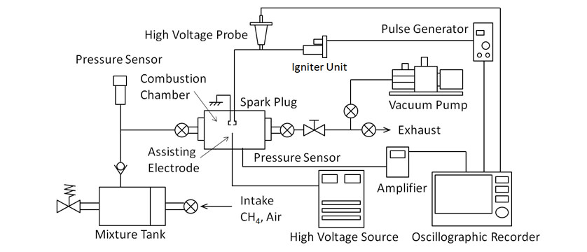
Fig. 1 shows a block diagram of the experimental apparatus, which consists of a mixture tank, constant-volume combustion chamber, igniter unit, and measurement system. The mixture in the mixture tank is continuously stirred by a stirrer driven by an external motor. This premixed gas is supplied from the tank to the constant-volume combustion chamber where it is ignited by the spark at the discharge gap of the experimental spark plug (described in detail below). The pressure in the combustion chamber is measured by a KISTRER 6061B piezo pressure sensor and recorded on data analyzing equipment. This apparatus also includes optics to enable Schlieren imaging to be performed in parallel with acquisition of pressure data. The voltage during spark discharge is measured by a Tektronix P6015 high-voltage probe.
3.2. Constant-Volume Combustion Chamber
The constant-volume combustion chamber consists of the body and heads that can be attached to both sides of the body. The chamber body is a stainless steel (SUS316) cylinder with a diameter of 74 mm and length of 74 mm. The combustion chamber volume is 318 cm3. It is designed such that the temperature of the chamber wall can be controlled as required using a 600-W band heater custom-built by Sakaguchi E.H VOC Corporation, a sheathed thermocouple, and a controller. The combustion chamber has holes for fitting the spark plug and pressure sensor. The combustion chamber heads are also made of SUS316 stainless steel and have quartz glass windows to enable Schlieren imaging. The two holes for fitting spark plugs are used for the experimental spark plug and the assisting electrode which applies the electric field in the combustion region.
3.3. Igniter Unit and Device for Applying Electric Field
A fully transistorized automotive igniter unit is used. The spark discharge energy is adjusted by using the width of pulses output from a pulse generator to control the duration of current flow through the primary coil.
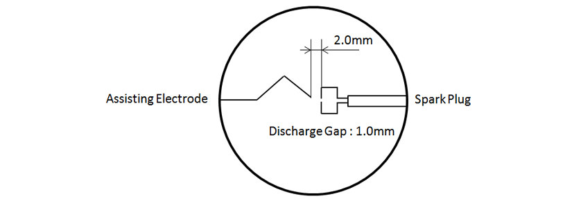
The experimental spark plug have a brass body and a Nilaco 905103 double-bore round insulating tube (external diameter: 4.0 mm, internal diameter: 1.0 mm) is used to provide insulation between the electrode and plug. The high-voltage and ground electrodes respectively of the spark plug are made by using two 0.8-mm diameters of nickel wire formed into a key shape and passing through each of these bores. The tips of the nickel wires are sharpened to stabilize the spark. The discharge gap is 1.0 mm and the distance between the discharge electrode and assisting electrodes was 2.0 mm. Fig. 2 shows the layout of the discharge electrode and assisting electrode.
A Matsusada Precision HCZE-30PN0.25 high-voltage power supply is used to apply the electric field in the combustion region. This power supply is able to generate positive and negative voltages of 30 kV.
4. Experimental Procedure
4.1. Experimental Conditions
The combustion tests use pure methane as the fuel and compressed air as the oxidant. Combustion tests are performed by adjusting the initial pressure and equivalence ratio in the combustion chamber as required and then triggering a spark in the experimental spark plug. Spark tests are performed by using compressed air to adjust the pressure in the chamber. When generating an electric field by applying a high voltage to the assisting electrode, the high-voltage power supply is operated continuously from just prior to ignition until combustion completed. The temperature of the chamber wall is maintained at a constant 300 K throughout the tests.
4.2. Definition of Minimum Current Flow Duration
It is not possible to perform combustion tests with the same high level of supercharging as an actual engine, due to the limited withstand pressure of the constant-volume combustion chamber. Accordingly, the ignition energy is reduced by shortening the duration of current flow through the primary coil to make adverse combustion region conditions for the spark plug. Preliminary combustion testing is performed in which the duration of current flow through the primary coil is changed to determine the minimum current flow duration for each set of initial pressure and equivalence ratio conditions. The minimum current flow duration is defined as the minimum duration of time that an ignition is not failed. In this case, ignition is performed 20 times in succession and the result treated as ignition failure if combustion failed to occur in even one time.
5. Results and Discussion
5.1. Electrostatic Migration of Initial Flame Kernel
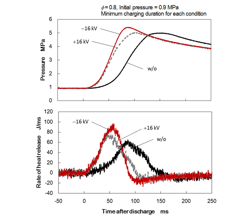
First, the influence of the electric field on growth of the initial flame kernel was investigated. The equivalence ratio of the methane/air mixture in the chamber was set to ø = 0.8 and the initial pressure to 0.9 MPa. The duration of current flow through the ignition coil was set to the minimum current flow duration for that set of conditions. The voltage applied to the assisting electrode was 16.0 kV and the test performed for both positive and negative polarity. Fig. 3 shows the pressure history and rate of heat release during the combustion tests. The results indicate that the pressure in the combustion chamber reached its maximum more rapidly in both the positive and negative voltage cases. Similarly, an analysis of the rate of heat release shows significant difference in the early stages of combustion in particular, indicating that the electric field had a major influence on growth of the initial flame kernel.
Fig. 4 shows Schlieren images captured during the test, at 1.0, 5.0, 10.0, 20.0, and 30.0 ms respectively after discharging a spark in the discharge gap.
An additional image at 40.0 ms is shown for the case when no electric field is applied. Comparing the images at 5.0 ms (immediately after ignition) indicates that, when an electric field is present, the flame flowed away from the tip of the assisting electrode during the initial stages of combustion and the growth of the flame kernel is faster. This is believed to be due to ions in the initial flame kernel being electrostatically transferred under the influence of the electric field, in line with the initial aim. This verified the electrostatic transfer effect of the initial flame kernel, one of the concepts of electric-field-assisted spark ignition.
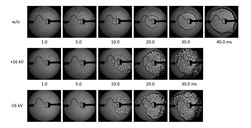
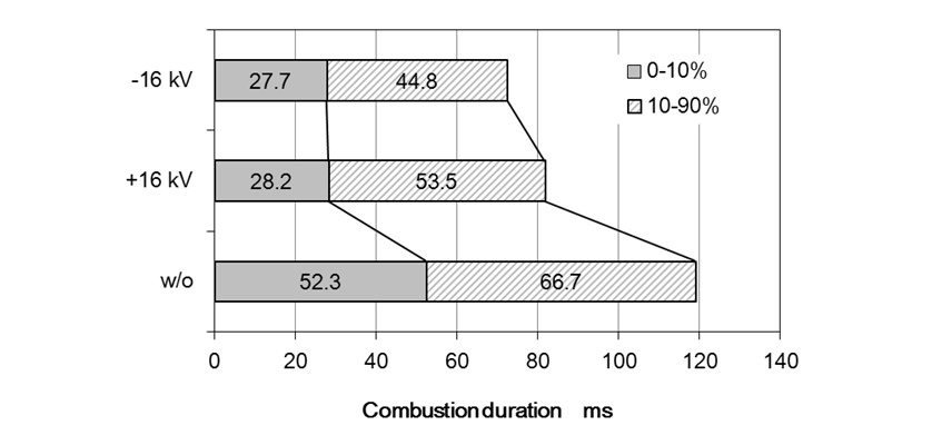
Looking at how flame propagation progresses indicates that the front of the flame surface is more wrinkled when the electric field is present than when it is not. Fig. 5 shows the combustion durations under the each condition. While the presence of an electric field has a large influence on initial combustion, as noted above, the main combustion period, during which 10 to 90% of combustion by mass occurs, is also shortened, indicating that combustion has been promoted.
Table 1 lists the minimum current flow durations for the different experimental conditions. Under these conditions, having an electric field present shortened the minimum current flow duration, regardless of whether the voltage was positive or negative. This effect was greater in the case of a positive voltage. This suggests the potential to improve ignition performance because ignition can be achieved with lower ignition energy.
Table1 Comparison of minimum charging duration at ø = 0.8
| Minimum charging duration[ms] | |
|---|---|
| w/o | 0.76 |
| +16 kV | 0.29 |
| - 16 kV | 0.62 |
5.2. Improving the Lean Burn Limit
Next, the equivalence ratio of the methane/air mixture in the chamber was set to ø = 0.6 to investigate the effect of an electric field on combustion in the vicinity of the lean burn limit. The voltage applied to the assisting electrode was 18.0 kV with positive polarity. The initial pressure in the chamber was 0.9 MPa, the same as in section 5.1.
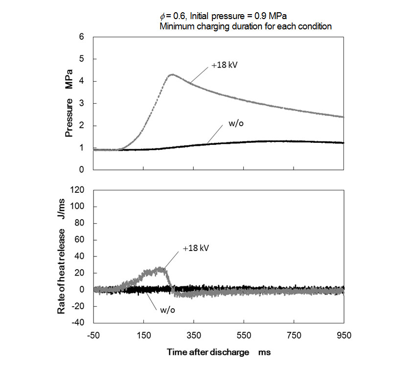
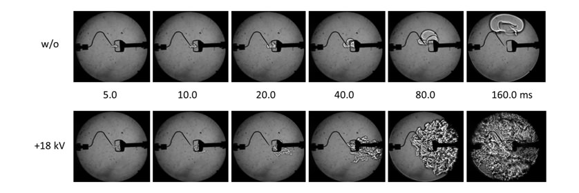
Fig. 6 shows the pressure history and rate of heat release during the combustion tests. The results indicate that the rise in pressure in the absence of an electric field is much weaker than is the case when ø = 0.8, indicating that conditions are close to the lean burn limit. When the electric field is present, however, combustion did occur. Fig. 7 shows the Schlieren images from this test. The images at 5.0 ms (immediately after ignition) show that, when an electric field is present, the initial flame kernel has already started flowing away from the assisting electrode. This indicates that the electrostatic transfer due to the electric field occurs even in the case of a lean mixture and that the initial flame kernel can rapidly be detached from the discharge gap. The images with presence of electric field from 20.0 to 80.0 ms after ignition show the initial flame kernel propagating rapidly with a wrinkled flame surface compared to the case without electric field. These results indicate that the electrostatic transfer of the initial flame kernel and the subsequent promotion of combustion noted in section 5.1 are also evident here.
This verified that electric-field-assisted spark ignition is an effective way to improve the lean burn limit.
5.3. Reduction in Breakdown Voltage
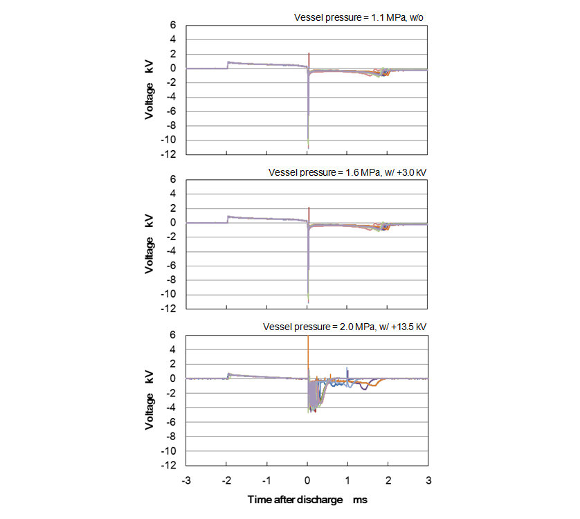
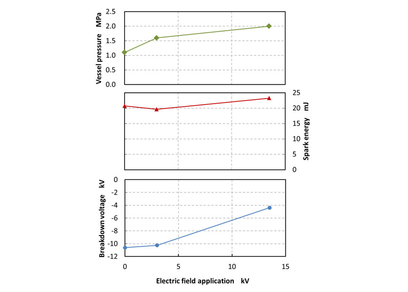
Next, to investigate the reduction in breakdown voltage, the chamber was filled with compressed air and spark testing was conducted at three different assisting electrode applying voltages: 0.0 kV (no voltage applied), +3.0 kV, and +13.5 kV. The duration of current flow through the primary coil was constant at 2.0 ms. Because the breakdown voltage of air is higher than that of a methane/air mixture, the pressure in the chamber was adjusted to the limit pressure at which the experimental spark plug can generate stable sparks. The mean breakdown voltage was determined from 10 times of sparking for each condition. Fig. 8 shows the discharge waveform under each test condition; Fig. 9 shows the limit pressure for discharge, spark energy, and mean breakdown voltage plotted against the voltage applied to the assisting electrode. While the absolute value of the mean breakdown voltage for an assisting electrode voltage of +3.0 kV is slightly smaller, there are no major differences in the discharge waveforms. However, the limit pressure for discharge increases from 1.1 MPa to 1.6 MPa. When the assisting electrode applying voltage is increased to +13.5 kV, a clear change becomes visible in the discharge waveform. The absolute value of the mean breakdown voltage also becomes significantly smaller, improving from −10.6 kV in the absence of an electric field to −4.4 kV. The limit pressure for discharge also increased to 2.0 MPa. Although the spark energy increased slightly from 20.7 mJ to 23.2 mJ, the difference is small.
This test verified the reduction in breakdown voltage, one of the concepts of electric-field-assisted spark ignition.
6. Conclusions
The authors have proposed the concept of electric-field-assisted spark ignition as a way to simultaneously expand the lean burn limit and reduce the breakdown voltage of spark ignition engines. Combustion and spark tests were conducted using a constant-volume combustion chamber to investigate the extent to which each of these objectives could be achieved. The conclusions are summarized below.
- (1)Applying an electric field in the discharge gap of the spark plug causes the initial flame kernel to detach rapidly due to the electrostatic transfer effect. This expands the lean burn limit.
- (2)The positive and negative high voltage applied to the assisting electrode are both effective.
- (3)The presence of an electric field when the spark plug discharges a spark reduces the breakdown voltage.
Acknowledgement
This research was assisted by Yuta Hishida who, at the time, was a student at the Graduate School of Engineering, Nagoya Institute of Technology. The authors would like to express their appreciation for his help.
References
- (1)Yuji Ikeda, Takeshi Serizawa, and Katsumi Uchida, “Improvement of Automotive Fuel Efficiency with Microwave Plasma Combustion,” Journal of the Japan Society of Mechanical Engineers, Vol. 117, No. 1148, p. 6-9 (2014) in Japanese.
- (2)Takashi Ito, Takaaki Hayashida, Kimitoshi Tanoue, Tatsuya Kuboyama, Yasuo Moriyoshi, Eiki Hotta, Naohiro Shimizu, “Very Lean and Diluted SI Combustion Using a Novel Ignition System with Repetitive Pulse Discharges,” Proceedings of 21st Internal Combustion Engine Symposium, p. 201-206 (2011) in Japanese.
- (3)Hiroaki Oi, Takeshi Serizawa, Fumio Okumura, “Experimental study on the performance of HF electric field applied-type ignition system in SI engine”, Proceedings of the Society of Automotive Engineers of Japan, No. 96-11, p. 5-12 (2011) in Japanese.
- (4)Kanemitsu Nishio, Yoshio Nakahara, “Knowledge and Characteristics of Spark Plugs”, Sankaido (1984) in Japanese.
-IMPORTANT-
The original technical report is written in Japanese.
This document was translated by R&D Management Division.
Author


Research & Development Center
Research & Development Unit
Ryoichi Hagiwara

Research & Development Center
Research & Development Unit (Ph.D.)
Toru Takemoto

Nagoya Institute of Technology (Assoc.Prof.)


