Development Division
Agricultural Operations Business
YANMAR Technical Review
Yanmar Combine Harvester Steering SystemFulltime Drive System (FDS)
1. Introduction
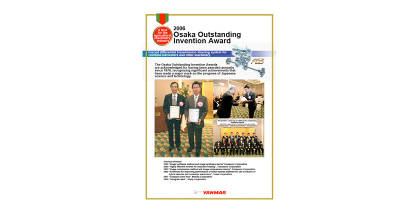
In 2006, Yanmar won the Osaka Outstanding Invention Award for its forced differential transmission steering system for combine harvesters and other machinery. The prize, which had previously been won for three years running (2003 to 2005) by Panasonic Corporation, is awarded to Osaka corporations in recognition of outstanding inventions that represent advances in science and technology. It was a memorial day in which our new steering system, which uses driving power for turning, was singled out from the field of agricultural machinery as worthy of recognition (see Fig. 1).
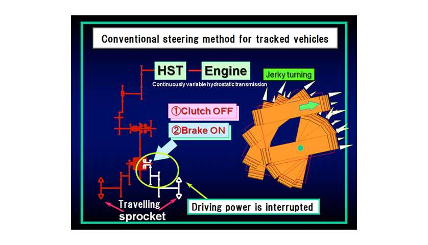
Yanmar has been supplying combine harvesters those are kinds of crop harvesting machinery since 1971. In the beginning most of these machineries used the mechanism by operating the clutch to change the speed for travelling and the mechanism by disengaging a side-clutch and applying a brake for turning. This is called the “clutch and brake steering” (see Fig. 2).
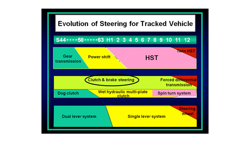
Subsequent technical advances in the thresher mechanism that separates husks from rice plants have boosted operating performance and increased vehicle working speeds. This has led to travelling systems being replaced by variable speed systems, resulting techniques such as power shift (multi-stage friction plate transmission) and variable-speed hydrostatic transmission (HST). In contrast, there have been no major changes in turning systems.
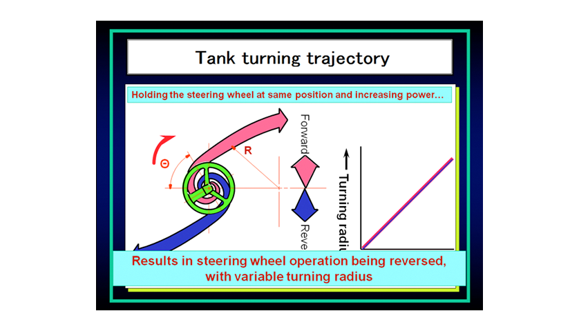
To improve turning systems so that they can keep pace with faster working speeds, Yanmar had studied the steering systems of military tank that uses crawler tracks as the references, resulting in the development of the forced differential transmission (see Fig. 3). However, in the case of using tank steering system :
- When travelling forward, turning the steering to the right turns the vehicle to the right
- When travelling backward, turning the steering to the right turns the vehicle to the left
Tanks are intended to drive forward in a straight line at high speed, only rarely being required to back into a garage or similar, and have opposite steering wheel operation to a passenger car (see Fig. 4) The way combine harvesters are used, however, involves frequent steering in both directions and therefore they need to have steering that works the same feeling as a car. Accordingly, Yanmar developed conical steering link. This succeeded in providing a turning system that felt more like that of a car by replacing the two levers or single lever that were previously used for steering with a steering wheel .
In this way, Yanmar had overcome the weaknesses of the clutch & brake steering by combining the forced differential transmission with the conical steering link to create the Fulltime Drive System (FDS) with steering wheel (see Fig. 5), which it has marketed since 1998.
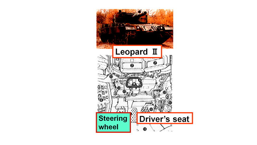
Source: Mechanic Books 14 Leopard Tanks
Publisher: Hara Shobo, Author: Ichiho Hamada
Published: September 10, 1987
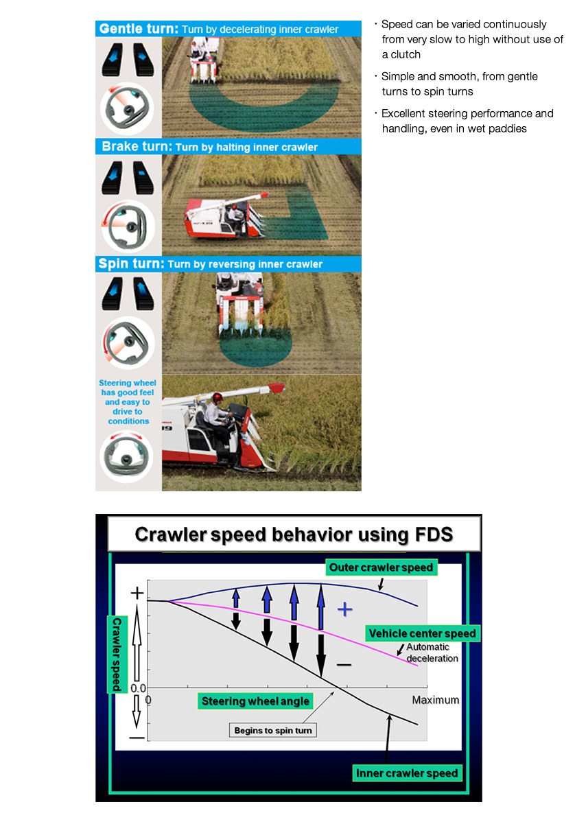
Utilizing the following three features:
- Continuously variable speed that can be achieved without using a clutch, from very slow up to high speeds
- Simple and smooth operation from gentle turn to spin turn
- Excellent turning and driving performance, even in wet paddies
Yanmar has also established FDS as a core technology, using it in tractors and other machinery as well as in its combine harvester product range.
This article introduces the forced differential transmission comparing with the clutch & brake steering and describes the matching mechanism for the steering operating method with steering wheel.
2. Transmission Used in Steering Systems
2.1. Features of Clutch & Brake Steering
When traveling straight, clutch & brake steering works by transmitting driving power to both right and left sides. When turning, the clutch on the inner side of the turn is disengaged to interrupt the driving power. This induces a gentle turn that enables the vehicle to be steered along the line of the planted crop. When a sharp turn is needed, such as at the edge of the field, it is achieved by breaking the drive wheel on the inner side of the turn (see Fig. 6).
Accordingly, next three are disadvantages in relation to steering performance, ability to operate in wet paddies, and durability.
- Steering performance
Smooth and precise turning is not possible because the turning radius depends on the clutch disengage timing and the level of braking, resulting in a jerky turning motion.
- Ability to operate in wet paddies
Because turning is performed by the driving one side only, with no driving power transmitting to the inner track, there is a loss of propulsion in wet paddy conditions to the extent that the vehicle may sometimes get stuck.
- Durability
Because the brake works using a friction plate, brake performance depends on the level of wear on the plate, making it difficult to maintain stable turning performance.
2.2. Features of Forced Differential Transmission
This section describes the steering mechanism, which is a major factor in steering performance.
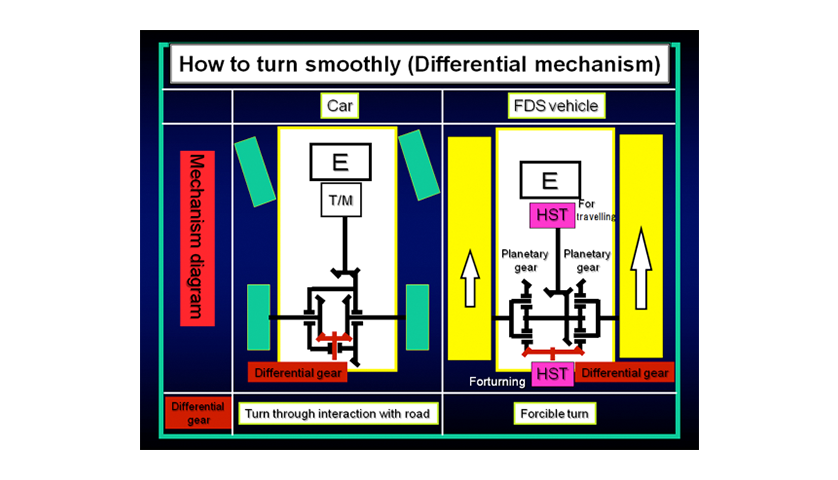
The differential gears used in cars are one way to enable smooth steering without jerkiness while the driving force is connected to both right and left wheels. When turning a car, the inner rear wheel rotates more slowly and the outer wheel rotates faster. The differential gear absorbs the difference of the speed. In contrast, forced differential transmission turns a vehicle by forcibly giving speed difference between the right and left track, a technique that can considerably improve steering performance. What is different from a car is that planetary gears are located on the right and left sides to generate a differential with the HST that applies the forced driving power in the fixed state (see Fig. 7).
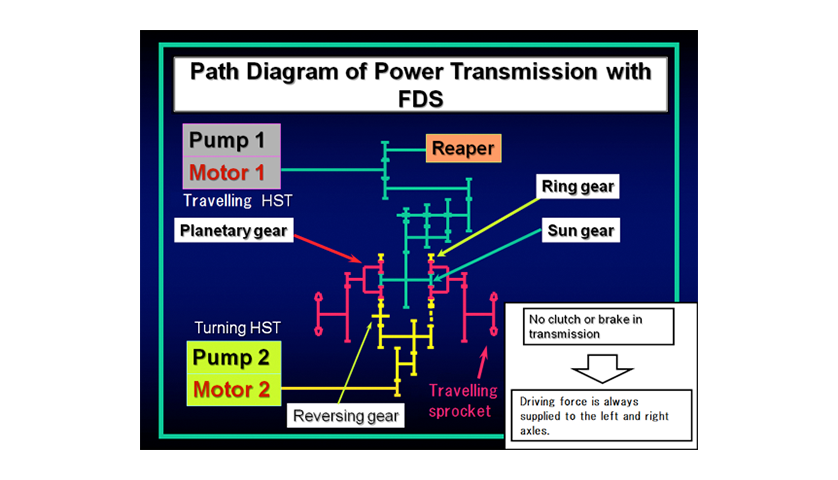
The next section describes the power transmission, which is a major factor in the ability to operate in wet paddies (see Fig. 8).
The HST that consists of pump 1 and motor 1 drives the vehicle forward or backward.
The output of motor 1 is input to the sun gears of the right and left planetary gear systems.
The HST that consists of pump 2 and motor 2 turns the vehicle.
The output of motor 2 is split in two, one output being used to drive the ring gear of the planetary gear system directly and the other to drive the ring gear via a reversing gear.
The rotation of motor 2 turns the ring gears in opposite directions.
The combined driving power of the sun gear and ring gear is transmitted to the left and right sprockets via the planetary carrier.
When traveling straight , halting motor 2 keeps the vehicle traveling straight forward.
When turning, the speed of motor 2 is gradually increased to turn smoothly.
Because this transmission mechanism has no clutch in the drive train, it provides fulltime drive with no interruption to the drive power to the right and left tracks regardless of the conditions.
Similarly, using no friction plates which is a major factor of durability ensures a high level of durability.
Accordingly, the use of forced differential transmission improves steering performance, ability to operate in wet paddies, and durability, each of which is weaknesses of clutch & brake steering.
3. Steering Operation
3.1. Conical Steering Link with steering wheel
As described above, the operating feeling aimed during development of the fulltime drive system was the feeling of a passenger car.
The feeling of a passenger car is as follows.
- The vehicle turns as expected according to the turning angles of steering wheel.
- The vehicle travels straight when the steering wheel is centered, without shaking.
- When traveling forward, turning the steering wheel to the right turns the vehicle to the right.
- When traveling backward, turning the steering wheel to the right turns the vehicle to the right.
- If the steering angle is constant, the turning radius remains constant, regardless of changes in vehicle speed.
All of these are taken for granted in passenger car.
However, combining the forced differential transmission steering system described above with a simple steering link has the following problems:
- Steering wheel operations in forward and reverse directions are opposite
- It is difficult to perform spin turns
- It is not possible to maintain a constant turning radius regardless of changes in vehicle speed
To overcome these problems, Yanmar developed the conical steering link.
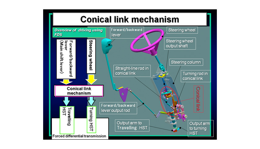
The outputs of the steering wheel and main speed control lever are once sent to a mechanical like calculator that is so called a conical link mechanism and then the output is input to the levers of the travelling HST and the turning HST (see Fig. 9).
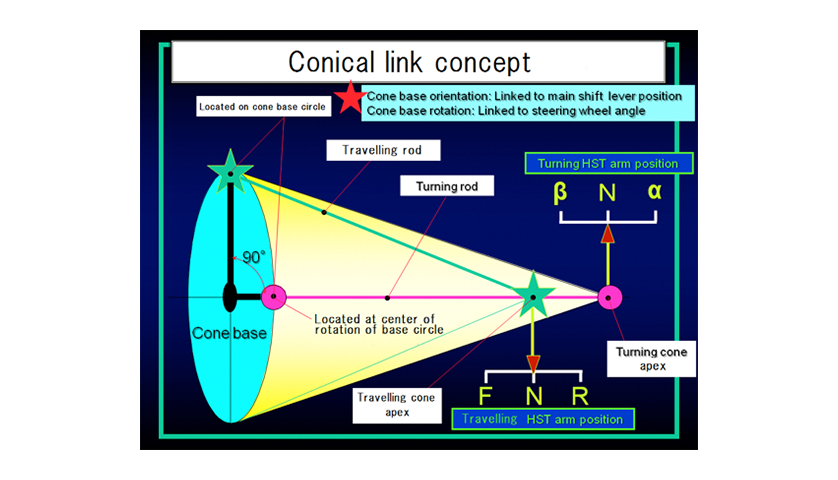
In the conical steering link (see Fig, 10 concept diagram), the ends of the travelling rod and turning rod are located at the base circle of the cone with a phase difference of 90°. The other ends of the rods are located at the apexes of the large and small cones.
The movements of the apexes of the travelling and turning cones are the positions of the travelling HST and turning HST control arms. Also, the turning angle of the forward/reverse lever is proportional to the inclination angle of the cone base, and the angle of the steering wheel is proportional to the rotation angle of the cone base. The figure shows the status when the vehicle is stationary.
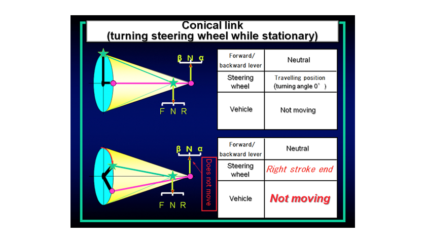
In Fig. 11, when the vehicle is stationary (upper figure), turning the steering wheel to the right changes the arrangement to that shown in the lower figure. Because the distance from the apex of the cone to its base circle remains constant throughout, the control arms of the travelling HST and turning HST do not move and no rotation occurs. In other words, the vehicle remains motionless.
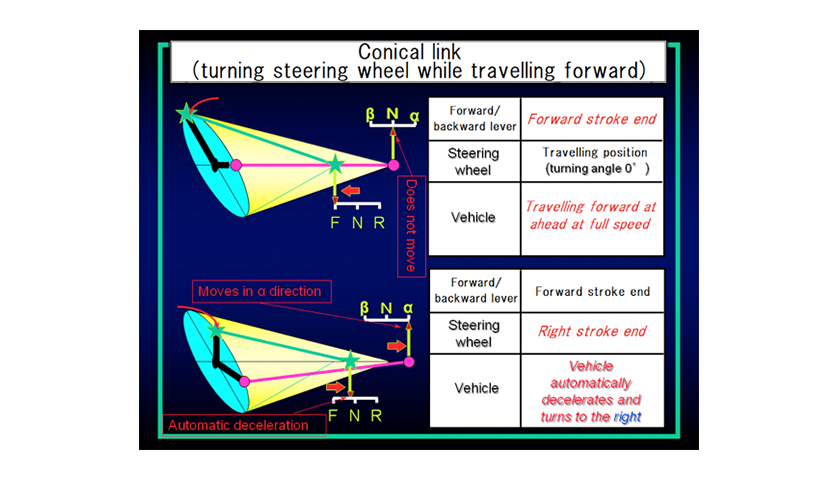
When the forward/reverse lever is then shifted forward, the arrangement changes to that shown in the upper figure in Fig. 12, with the control arm of the travelling HST moving to the F position. However, the control arm of the turning HST does not move because the end of the turning rod is located on the center line of base turning. In other words, the vehicle is on the condition of forward straight.
When the steering wheel is then turned to the right, the control arm of the travelling HST moves to the slower speed direction and the control arm of the turning HST to the direction α. That is, turning the steering wheel turns the vehicle to the right while at the same time automatically reducing its speed. In this case, the control arm of the turning HST moves to the direction α.
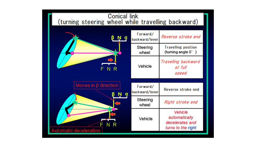
In Fig. 13, when the vehicle is reversing, it travels backward straight shown in the upper figure because the control arm of the turning HST does not move same as the case of travelling forward. If the steering wheel is then turned to the right, the control arm of the travelling HST decelerates automatically as well. This time, however, the control arm of the turning HST moves in the direction β, the opposite to the case when travelling forward.
The operations of the turning HST in the forward and reverse directions are opposite. This explains how the problem of the steering wheel having the opposite effect depending on the direction of movement has been overcome.
In this way, the conical steering link with steering wheel utilizes the simple principle that the distance from the apex to the base circle of a cone is always constant to realize the operation with the feeling of passenger car. It also provides an entirely mechanical solution to the three problems quoted above, namely the steering wheel operation in the forward and reverse directions being opposite, the difficulty of performing spin turns, and the inability to maintain a constant turning radius regardless of changes in vehicle speed. This technology is proprietary to Yanmar and is unparalleled anywhere in the world.
3.2. Ring Cam Steering Link
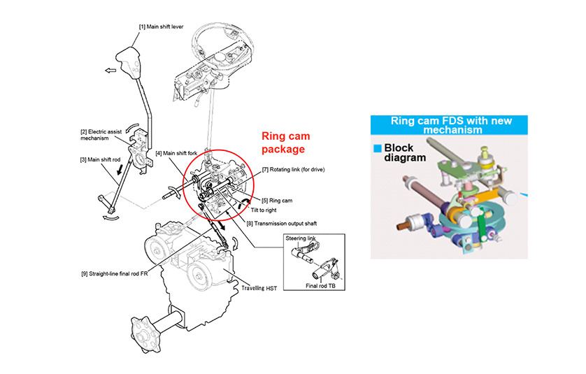
Since the commercialization of the fulltime drive system, the large number of parts used in the conical steering link has created a need to further reduce its cost. Reliability improvements have also been required due to the large number of adjustment points. To achieve this, Yanmar commercialized a ring cam steering link accomplished reducing the number of components in 2011 (see Fig. 14).
This method is a steering link that incorporates a cam and derives from the idea of forming a disk(ring) by compressing everything in the axial direction of the cone. In addition to being less costly than the conical steering link, it also provides better steering feel by reducing the amount of play in each of the parts. Because the entire mechanism can fit inside a compact case, it also improves comfortability by enabling more step space legroom. Reliability, too, is improved by a significant reduction in the number of adjustment points.
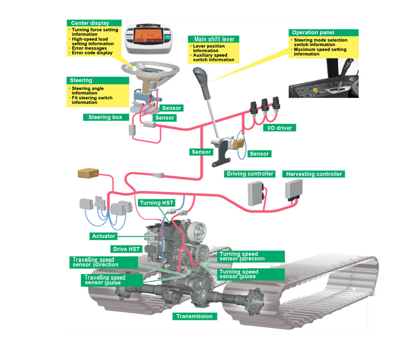
3.3. Steer by Wire
Yanmar’s flagship combine harvester released in 2012 installs an electronically controlled steering system (with no mechanical steering link) to satisfy the demanding requirements of Japanese customers for very fast operation and long time of work. In addition to enabling the steering feeling to be customized (switched between different options), the new system also reduces the operating force needed for steering. Eliminating the link that connects the steering to the transmission also allows the cabin holes to be closed in, improving sound-proofing and dust-proofing (see Fig. 15).
4. Conclusions
Because conventional combine harvesters developed in Europe and America primarily for harvesting wheat are not particularly suitable for harvesting rice in Japan, a head-feeding combine harvester designed specifically for use in Japan was developed in 1966. Subsequently, speed was increased by enhancements to a more energy-efficient threshing method. Associated improvements were made to the driving and steering systems, with the steering systems described in this article being commercialized as core proprietary technologies of Yanmar.
In the future, Yanmar intends to continue challenging on new technology to improve combine harvesters and on advances in harvesting technology.
-IMPORTANT-
The original technical report is written in Japanese.
This document was translated by R&D Management Division.
Author